ASE Home
Resources
Compressed gas
Regulators
Low pressure gas
Quick-flush
Flowmeters
Vaporizers
Breathing systems
Non-rebreathing
Rebreathing
Waters' canister
Ventilators
Endotracheal tubes
Scavenging
Anesthesia Service and Equipment

Circle Absorber

Construction

Circle Absorber

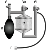
The essential features of the circle absorber are: a carbon dioxide absorber canister (C), breathing bag (B), unidirectional inspiratory (Vi) and expiratory (Ve) valves, fresh gas supply (F) and pressure-relief valve (V). The absorber is connected to the patient via corrugated hoses and a Y-piece (not shown) attached to the inspiratory and expiratory valves (Vi and Ve).
   The position of the breathing bag and pressure-relief valve may vary in relation to the absorber, but the above is a common and satisfactory arrangement.

Function

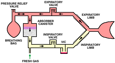
Circle Absorber Function

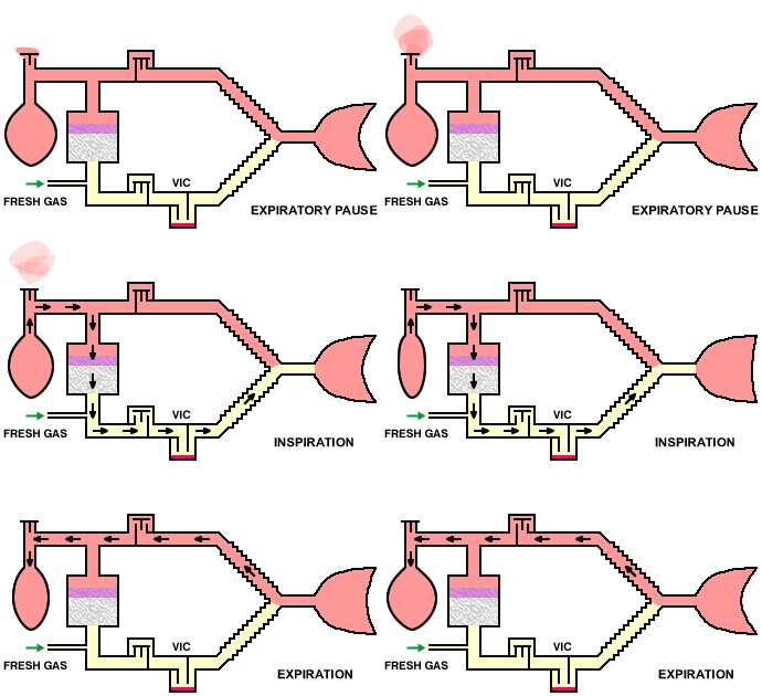
Inspiration: Inspiration causes the expiratory valve to close and gas flows from the breathing bag to the patient via the inspiratory limb of the circuit. Anesthetic is taken up from the in-circuit vaporizer (VIC), if fitted.
Expiration: The inspiratory valve closes and gas flows into the breathing bag via the expiratory limb. Carbon dioxide is absorbed by the soda lime canister. Excess gas is vented when necessary via the pressure-relief valve.

Closed and semi-closed

The circle absorber may be used as a closed or semi-closed system:

  • Closed systems: the pressure relief valve is closed so that no gas escapes from the system. Oxygen flows into the system to replace that consumed by the patient and exhaled carbon dioxide is absorbed by the soda lime.


    The advantage of closed systems is that anesthetic and oxygen consumption, and atmopsheric pollution, are minimized.
        The disadvantages are:
    (a) the system is inherently unstable, in that if the fresh gas flow is not matched exactly to the patient's oxygen consumption, the system will over-fill or empty, and the patient will be unable to breathe.
    (b) the fresh gas flow rate is usually too small to allow use of a precision, out of circuit vaporizer.
  • Semi-closed systems: the pressure relief valve is opened allowing excess gas to escape from the system. This allows higher fresh gas flow rates to be used.


      The advantages of semi-closed systems are:
    (a) The system is more stable in that, if the system fills to capacity, the excess gas is simply lost via the pressure relief valve.
    (b) The higher flow rates allow use of a precision, out of circuit vaporizer.
       The disavantage is increased anesthetic and oxygen consumption and atmospheric pollution.

Canister gas flow

Most modern canisters are orientated vertically, which facilitates changing the absorbant and avoids the problems of channelling encountered with horizontal canisters (as described under the Waters' Canister). In most absorbers, gas flows from the top to the bottom of the canister, although in some gas flows from the bottom to the top.
    
The advantage of top-to-bottom flow is that flow tends to be preferentially directed down the walls of the canister (owing to the lower resistance of absorbent granules located against the smooth wall of the canister), so color-change due to exhaustion of the absorbant is easily detected. Conversely, the color change in bottom-to-top flow canisters starts in the middle of the absorber where it cannot be seen.

Furthermore, in bottom-to-top flow absorbers, condensed water vapor tends to accumulate at the bottom of the canister and may cause the absorbant to become water-logged. In top-to-bottom flow absorbers, gravity leads to more even distribution of condensed water vapor throughout the absorbant.

Unidirectional valves

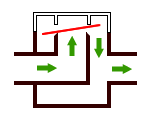
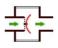
The unidirectional inspiratory and expiratory valves in most circle absorbers are of the turret type, in which the pressure generated by the patient's breathing causes the disc to rise and allow gas to pass in one direction only. Most have a transparent dome so that the operation of the valve may be observed.

The disc material may be mica, ceramic or plastic. Plastic is less expensive, but tends to warp and allow the valve to become incompetent. Incompetence may also be caused by the valve sticking in the open position owing to condensation of water vapor. Incompetent inspiratory or expiratory valves will reduce the efficiency of gas circulation and result in rebreathing and consequent carbon dioxide retention.

Some machines are equipped with valves made of deformable rubber:

As the rubber ages, these discs tend to harden in a semi-open position, again allowing the valve to become incompetent.

Connecting tubing

The body of the absorber is connected to the patient by means of inspiratory and expiratory tubes and a Y-piece. This may be constructed of corrugated black rubber, neoprene or, more recently, plastic.

Recently, the so-called Universal F circuit has become popular. This is a co-axial system, the inspiratory tube running inside the expiratory limb:

This arrangement aids warming and humidification of the inspired gases, albeit at the expense of an increase in inspiratory resistance to breathing. One problem with this system, as with other co-axial circuits, is that, if the inner tube breaks or becomes disconnected at the absorber end (which may not be noticed on casual inspection), the entire volume of the tube becomes apparatus dead space. It should also be noted that, in all other aspects, this system is identical in function to a conventional, dual-limb system, and does not provide an economical alternative to the Bain system (although it is occasionally marketed as doing so).

Patient Size

Most circle absorbers constructed for use in human-sized animals are satisfactory for use in patients weighing up to around 100 kg. For larger animals (e.g. horses and cattle), purpose-built large animal absorbers should be used. These have larger absorber canisters and larger tubing and valves in order to reduce resistance to breathing.
    The major problem with using standard circle absorbers in very small animals is that of dead space. First, animals with very small tidal volumes may not generate enough pressure to open the valves effectively. Secondly
, the effective dead space of the Y-piece is larger than it appears. Inevitably, some portion of the expired gas is directed down the inspiratory limb of the circuit, and some portion of the inspired gas comes from the expiratory limb, and some mixing of inspired and expired gases occurs. This may be avoided by placing the valves in the Y-piece itself, but this arrangement is clumsy and little used.

(a) Apparent dead space
(b) Expired gas
(c) Effective dead space

These difficulties may be reduced by the use of purpose-built infant absorbers, which are smaller than the standard models. Pediatric tubing and Y-pieces, which are simply smaller in diameter than the standard type, may be helpful. Purpose-built fans may also be used to circulate the gases, but these are not comonly encountered in veterinary practice.

In- and out-of-circuit vaporizers

An inhalation anesthetic agent may be supplied from a vaporizer positioned in the circle itself (vaporizer in circuit, VIC) or in the fresh gas flow from the anesthetic machine (vaporizer out of circuit, VOC).

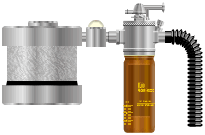
  • Vaporizer in circuit arrangements have a low-resistance vaporizer placed in the inspiratory limb of the circle, from which the anesthetic agent is vaporized by the gases circulated around the system by the animal's breathing.

       VIC systems are still used in veterinary practice since they employ an inexpensive vaporizer and provide some degree of autoregulation of the anesthetic concentration. If the plane of anesthesia becomes too light, respiration will be less depressed, minute volume will increase, more agent will be vaporized and the plane of anesthesia will deepen. It is, however, found that this is not very reliable in practice.
       Although low-resistance vaporizers are usually relatively inefficient (with the output of, for example, halothane limited to around 2.5 to 3%), the concentration of anesthetic inspired by the patient may be very much higher than this because the gas entering the vaporizer also contains anesthetic from previous circulations. Indeed, after full equilibration of the circuit and patient, the inspired concentration would equal the SVP of the anesthetic, although obviously the patient would have expired long before this point was reached. It is therefore strongly recommended that an inhalation anesthetic analyzer be used to monitor the inspired concentration whenever such systems are used.
       In-circuit vaporizers can be used with closed or semi-closed systems.

       Since water vapor exhaled by the patient condenses in the vaporizer, it is necessary to drain in-circuit vaporizers regularly.

  • Vaporizer out of circuit systems have the considerable advantage that a precision vaporizer may be used to introduce a precisely-known concentration of anesthetic into the circuit. However, since this delivered concentration is diluted by the gas already contained in the circuit, the concentration inspired by the patient is not known with certainty.
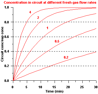
       The rate of change of anesthetic concentration in the circuit depends upon the fresh gas flow rate: a high fresh gas flow rate will achieve equilibration much faster than if a low fresh gas flow rate is used:

The above graph shows anesthetic concentrations in a typical small-animal circle system as a fraction of the out-of-circuit vaporizer concentration, using different fresh gas flow rates (0.2 to 4 l/min). When low flow rates are employed, the concentration of anesthetic in the circuit will change very slowly, which may cause difficulty in maintaining a satisfactory plane of anesthesia.
    Out of circuit vaporizers are usually used in semi-closed systems: the low fresh gas flow rate required in closed systems usually makes their use impractical.

Double-canister absorbers

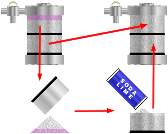
Many absorbers designed for use in human patients employ two canisters placed in series: the top canister is exposed to the expired gases first and removes most of the carbon dioxide. Any remaining carbon dioxide is then removed by the bottom canister. When the top canister is exhausted, the absorbent is discarded, the bottom canister is placed in the top position and a canister with fresh absorbent is inserted underneath it. This arrangement provides optimal efficiency and economy in carbon dioxide absorption. However, these absorbers are bulkier, heavier and more expensive than single-canister models.


If this type of absorber is used, it is a false economy to fill only one of the two canisters. The soda-lime will be exhausted at the same rate, efficiency of absorption will be reduced, and the greater volume of the circuit will delay equilibration of the gas in the circuit with the fresh gas supplied from the anesthetic machine. This will not only slow induction and recovery, but will also tend to increase consumption of the inhalation anesthetic.

Operational requirements

  • The volume of the breathing bag must be greater than the patient's inspiratory capacity. This is usually estimated at 30 ml/kg body weight.
  • Since soda lime contains 50% - 70% air around the granules, the volume of the absorber canister should be at least double that of the tidal volume of the patient for optimal efficiency.
  • Fresh gas flow requirements--see separate article for closed and semi-closed systems.
  • The normal circle system is not suitable for very small animals (less than about 10 kg) since their tidal and minute volumes are too small to circulate gas effectively.

Advantages of the circle system

  • Economy of anesthetic consumption.
  • Warming and humidification of the inspired gases.
  • Reduced atmospheric pollution.
  • More efficient use of soda lime than in Waters' canister.

Disadvantages

  • Expensive and rather bulky.
  • Unstable if used closed.
  • Slow changes in the inspired anesthetic concentration with low flows and out-of-circuit vaporizer.
  • The soda lime and valves in the system increase resistance to breathing.
  • Inhalation of soda-lime dust.

Uses

  • Small animals over 10 kg, large animals.

Waters' canister  

Comments on this article should be addressed to Dr Guy Watney
All pages © Anesthesia Service and Equipment 1998-2003.